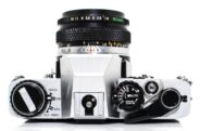
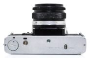
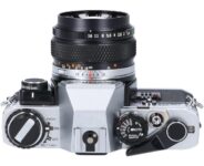
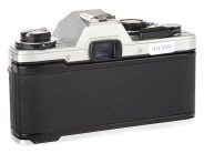
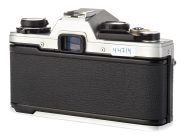
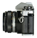
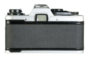
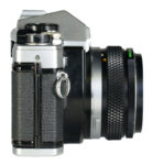
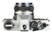
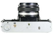
Olympus OM10

35mm MF film SLR camera

Specification

Production details:
Announced:1979
System: Olympus OM (1972)
Format:
Maximum format:35mm full frame
Film type:135 cartridge-loaded film
Mount and Flange focal distance:Olympus OM [46mm]
Shutter:
Type:Focal-plane
Model:Electronically controlled
Speeds:2 - 1/1000
Exposure:
Exposure metering:Through-the-lens (TTL), open-aperture
Exposure modes:Aperture-priority Auto
Physical characteristics:
Weight:430g
Dimensions:135x84x50mm

Manufacturer description #1

Join the electronic camera age. Forget the fiddling and worrying that rob photography of so much pleasure - and far too many fine pictures. But don't forget the performance and versatility every professional rightly insists on. That's the invitation of the fantastic OLYMPUS OM-10. A 35SLR camera that's extraordinarily light and compact. But utilizes electronic circuitry so sophisticated and reliable, exposure errors and photographer slip-ups are next to impossible. A camera with superb system versatility to bring any subject, anywhere, into your range - in the acclaimed OLYMPUS OM tradition.

The OLYMPUS OM-10. A masterpiece of failsafe electronic functionality.

Nothing is quite so frustrating as capturing a unique photographic opportunity - only to find you forgot a setting, and ruined the picture. Everyone forgets sometimes, but the unparalleled array of electronic monitor and control devices built into the OM-10 guarantees it won't cause you any lost opportunities.

Extra Powerful Twin Electrondc Brains

To handle its various automatic functions, the OM-10 utilizes two newly developed, high input impedance, high speed bipolar MSI Central Processing Units as twin electronic brains, which control shutler speeds and viewfinder display independently. Highly efficient and reliable new circuitry eliminates the need for the exposure control condenser of conventional auto SLRs. A unique feature of the input mechanism is ultra fast response utilizing the TTL Direct Light Measuring method.

TTL Direct Light Measuring

Created and perfected by OLYMPUS, pioneered in the sensational OM-2, TTL Direct Light Measuring is the only auto exposure system that works on real time.

In the viewfinder of a single lens reflex camera (SLR), you see an image captured by the lens, then reflected up by the mirror and through the pentaprism. When you press the shutler butlon, the mirror swings up to allow this image to reach the film. In normal SLRs, the light measuring cells are located in the viewfinder section, so when the mirror swings up, they are cut off from the image and can no longer read the light value. To control the exposure, they have to read the light before you take the picture, and store the information in a memory device. If the light changes suddenly, they get the exposure wrong.

In the OM-10 the light cell, an ultra-sensitive SBC, is located in the front of the camera pointing backwards. It starts working AFTER the mirror is raised, and directly reads the light that hits the film plane, DURING the exposure. This SBC is monitored by the electronic brain, which flicks the shutler closed at the exact instant enough light has been allowed through. Naturally TTL Direct Light Measuring needs no memory device, making it not only more accurate, but simpler and more reliable too. It's a system that just can't go wrong.

Random Pattern Shutter

A computer-generated random digital patlern on the shutler curtain enables the SBC light cell to obtain a perfectly balanced exposure reading.

Light and Sound - Unique Twin Indicator System

The OM-10 is the first camera in the world to feature a foolproof audio-visual indicator system. A Piezoelectric Ceramic Vibrator (PCV) combines with a super bright GaAlAs LED to indicate battery check and self-timer operation, emitting continuous or intermittent electronic tone and warning light. This provides an unmistakable dual function check in light or dark conditions.

Automatic Flash Setting

The OM-10's electronic brain automatically sets the correct shutter speed of 1/60 sec. when the special T20 electronic flash unit is fitted to the camera hot shoe and switched on.

Multi-Function Viewfinder Display

The viewfinder of the OM-10 is designed to be as simple as possible in order to avoid distracting the photographer. But it also conveys a wealth of useful information. A series of LEDs along the left hand margin provides an instant shutter speed indication (from 1/1,000 sec. to 1 sec.). Another LED above this display indicates over-exposures. Above the shutter speed indication is one more LED, which lights up to show when the T20 electronic flash is fully charged. A unique feature is the correct flash exposure check function. After the flash has been correctly exposed, the LED blinks repeatedly to confirm the picture will turn out as expected.

Special, Energy-Saving Preview Switch

The viewfinder LED display is activated in three different ways: by turning the Selector Dial to ON, by lightly pressing the shutter release button prior to taking the picture, or by lightly touching the special switch projecting alongside the release button. The display switches off automatically 90 seconds later in order to conserve the batteries.

Mode-Override Safety Device

Even if you forget to switch the Selector Dial to ON, a special safety device will assure proper automatic exposure of your pictures.

Automatic Shutter Lock

If the batteries are exhausted, an electromagnetic safety device automatically locks the shutter. It re-opens when new batteries are inserted.

Manufacturer description #2

The Olympus OM-10 is a single lens reflex camera of the finest quality in which the automation of photographic functions has been made possible by employing the most advanced electronics. To its acceptability of Olympus interchangeable lenses, a special film winder, a flash, and a host of other accessories are added to make it a complete system of photography. With the OM-10 you can gradually widen your enjoyment of the photographic art.

***

CAMERA TYPE: 35mm single lens reflex camera with electronic control automatic exposure and focal plane shutter.

IMAGE FORMAT: 24 x 36mm.

LENS MOUNT: Olympus OM Mount, bayonet type.

SHUTTER: Electronically controlled focal plane shutter.

FLASH SYNCHRONIZATION: X contact. Direct contact only.

AUTOMATIC EXPOSURE CONTROL: Aperture-priority electronically controlled shutter. TTL direct light measuring system. Light measuring range: EV-0.5 to 18 from 2 sec. to 1/1000 sec. at normal temperatures and humidity with ASA 100 and F1.2 standard lens. Exposure compensation: ±2EV. Automatic flash exposure: Normal auto flash (at 2 aperture settings F4 and F8 with ASA 100 film) is automatically set to X synch. (1/ 60 sec.) in conjunction with the electronic flash T20.

MANUAL EXPOSURE CONTROL: The optional Manual Adapter attached to the OM-10 permits a full range of 11 manual shutter speeds. (1 to 1/1,000 sec.). By setting the mode selector lever to the manual mode, the shutter speed can be set to 1/60 sec.

FILM SPEED RANGE: ASA 25 to 1600.

BATTERY CHECKER: Battery voltage can be checked by both LED and PCV. Mirror lock to limit drainage.

POWER SOURCE: Two 1.5V alkaline-manganese batteries LR44 (A76), or two 1.5V silver oxide batteries SR44 (Eveready EPX-76 or equivalents).

VIEWFINDER: Pentaprism type.

FOCUSING SCREEN: Microprism/sprit image-matte type.

FINDER VIEW-FIELD: 93% of actual picture field.

VIEWFINDER MAGNIFICATION: 0.92X with the 50mm lens at infinity.

VIEWFINDER INFORMATION: 12-step shutter speed scale and flash charge indicated by LEDs.

MIRROR: Oversize, quick return mirror.

FILM ADVANCE: Lever type with 130° angle, It can be wound with one long or several short strokes. 30° pre-advance angle. Power winding is possible with the Olympus OM System Winder 2.

SELF-TIMER: Electronic self-timer with about 12 second delay.

ACCESSORY SHOE: Built-in type, with direct contact.

Subscribe
Notify of
guest

Copy this code

and paste it here *

0 comments
Inline Feedbacks
View all comments

Copyright © 2012-2024 Evgenii Artemov. All rights reserved. Translation and/or reproduction of website materials in any form, including the Internet, is prohibited without the express written permission of the website owner.

Chromatic aberration

There are two kinds of chromatic aberration: longitudinal and lateral. Longitudinal chromatic aberration is a variation in location of the image plane with changes in wave lengths. It produces the image point surrounded by different colors which result in a blurred image in black-and-white pictures. Lateral chromatic aberration is a variation in image size or magnification with wave length. This aberration does not appear at axial image points but toward the surrounding area, proportional to the distance from the center of the image field. Stopping down the lens has only a limited effect on these aberrations.

Spherical aberration

Spherical aberration is caused because the lens is round and the film or image sensor is flat. Light entering the edge of the lens is more severely refracted than light entering the center of the lens. This results in a blurred image, and also causes flare (non-image forming internal reflections). Stopping down the lens minimizes spherical aberration and flare, but introduces diffraction.

Astigmatism

Astigmatism in a lens causes a point in the subject to be reproduced as a line in the image. The effect becomes worse towards the corner of the image. Stopping down the lens has very little effect.

Coma

Coma in a lens causes a circular shape in the subject to be reproduced as an oval shape in the image. Stopping down the lens has almost no effect.

Curvature of field

Curvature of field is the inability of a lens to produce a flat image of a flat subject. The image is formed instead on a curved surface. If the center of the image is in focus, the edges are out of focus and vice versa. Stopping down the lens has a limited effect.

Distortion

Distortion is the inability of a lens to capture lines as straight across the entire image area. Barrel distortion causes straight lines at the edges of the frame to bow toward the center of the image, producing a barrel shape. Pincushion distortion causes straight lines at the edges of the frame to curve in toward the lens axis. Distortion, whether barrel or pincushion type, is caused by differences in magnification; stopping down the lens has no effect at all.

The term "distortion" is also sometimes used instead of the term "aberration". In this case, other types of optical aberrations may also be meant, not necessarily geometric distortion.

Diffraction

Classically, light is thought of as always traveling in straight lines, but in reality, light waves tend to bend around nearby barriers, spreading out in the process. This phenomenon is known as diffraction and occurs when a light wave passes by a corner or through an opening. Diffraction plays a paramount role in limiting the resolving power of any lens.

Doublet

Doublet is a lens design comprised of two elements grouped together. Sometimes the two elements are cemented together, and other times they are separated by an air gap. Examples of this type of lens include achromatic close-up lenses.

Dynamic range

Dynamic range is the maximum range of tones, from darkest shadows to brightest highlights, that can be produced by a device or perceived in an image. Also called tonal range.

Resolving power

Resolving power is the ability of a lens, photographic emulsion or imaging sensor to distinguish fine detail. Resolving power is expressed in terms of lines per millimeter that are distinctly recorded in the final image.

Vignetting

Vignetting is the darkening of the corners of an image relative to the center of the image. There are three types of vignetting: optical, mechanical, and natural vignetting.

Optical vignetting is caused by the physical dimensions of a multi-element lens. Rear elements are shaded by elements in front of them, which reduces the effective lens opening for off-axis incident light. The result is a gradual decrease of the light intensity towards the image periphery. Optical vignetting is sensitive to the aperture and can be completely cured by stopping down the lens. Two or three stops are usually sufficient.

Mechanical vignetting occurs when light beams are partially blocked by external objects such as thick or stacked filters, secondary lenses, and improper lens hoods.

Natural vignetting (also known as natural illumination falloff) is not due to the blocking of light rays. The falloff is approximated by the "cosine fourth" law of illumination falloff. Wide-angle rangefinder designs are particularly prone to natural vignetting. Stopping down the lens cannot cure it.

Flare

Bright shapes or lack of contrast caused when light is scattered by the surface of the lens or reflected off the interior surfaces of the lens barrel. This is most often seen when the lens is pointed toward the sun or another bright light source. Flare can be minimized by using anti-reflection coatings, light baffles, or a lens hood.

Ghosting

Glowing patches of light that appear in a photograph due to lens flare.

Retrofocus design

Design with negative lens group(s) positioned in front of the diaphragm and positive lens group(s) positioned at the rear of the diaphragm. This provides a short focal length with a long back focus or lens-to-film distance, allowing for movement of the reflex mirror in SLR cameras. Sometimes called an inverted telephoto lens.

Anastigmat

A photographic lens completely corrected for the three main optical aberrations: spherical aberration, coma, and astigmatism.

By the mid-20th century, the vast majority of lenses were close to being anastigmatic, so most manufacturers stopped including this characteristic in lens names and/or descriptions and focused on advertising other features (anti-reflection coating, for example).

Rectilinear design

Design that does not introduce significant distortion, especially ultra-wide angle lenses that preserve straight lines and do not curve them (unlike a fisheye lens, for instance).

Focus shift

A change in the position of the plane of optimal focus, generally due to a change in focal length when using a zoom lens, and in some lenses, with a change in aperture.

Transmittance

The amount of light that passes through a lens without being either absorbed by the glass or being reflected by glass/air surfaces.

Modulation Transfer Function (MTF)

When optical designers attempt to compare the performance of optical systems, a commonly used measure is the modulation transfer function (MTF).

The components of MTF are:

The MTF of a lens is a measurement of its ability to transfer contrast at a particular resolution from the object to the image. In other words, MTF is a way to incorporate resolution and contrast into a single specification.

Knowing the MTF curves of each photographic lens and camera sensor within a system allows a designer to make the appropriate selection when optimizing for a particular resolution.

Veiling glare

Lens flare that causes loss of contrast over part or all of the image.

Anti-reflection coating

When light enters or exits an uncoated lens approximately 5% of the light is reflected back at each lens-air boundary due to the difference in refractive index. This reflected light causes flare and ghosting, which results in deterioration of image quality. To counter this, a vapor-deposited coating that reduces light reflection is applied to the lens surface. Early coatings consisted of a single thin film with the correct refractive index differences to cancel out reflections. Multi-layer coatings, introduced in the early 1970s, are made up of several such films.

Benefits of anti-reflection coating:

Circular fisheye

Produces a 180° angle of view in all directions (horizontal, vertical and diagonal).

The image circle of the lens is inscribed in the image frame.

Diagonal (full-frame) fisheye

Covers the entire image frame. For this reason diagonal fisheye lenses are often called full-frame fisheyes.

Extension ring

Extension rings can be used singly or in combination to vary the reproduction ratio of lenses. They are mounted between the camera body and the lens. As a rule, the effect becomes stronger the shorter the focal length of the lens in use, and the longer the focal length of the extension ring.

View camera

A large-format camera with a ground-glass viewfinder at the image plane for viewing and focusing. The photographer must stick his head under a cloth hood in order to see the image projected on the ground glass. Because of their 4x5-inch (or larger) negatives, these cameras can produce extremely high-quality results. View cameras also usually support movements.

135 cartridge-loaded film

43.27 24 36
  • Introduced: 1934
  • Frame size: 36 × 24mm
  • Aspect ratio: 3:2
  • Diagonal: 43.27mm
  • Area: 864mm2
  • Double perforated
  • 8 perforations per frame

120 roll film

71.22 44 56
  • Introduced: 1901
  • Frame size: 56 × 44mm
  • Aspect ratio: 11:14
  • Diagonal: 71.22mm
  • Area: 2464mm2
  • Unperforated

120 roll film

79.2 56 56
  • Introduced: 1901
  • Frame size: 56 × 56mm
  • Aspect ratio: 1:1
  • Diagonal: 79.2mm
  • Area: 3136mm2
  • Unperforated

120 roll film

89.64 56 70
  • Introduced: 1901
  • Frame size: 70 × 56mm
  • Aspect ratio: 5:4
  • Diagonal: 89.64mm
  • Area: 3920mm2
  • Unperforated

220 roll film

71.22 44 56
  • Introduced: 1965
  • Frame size: 56 × 44mm
  • Aspect ratio: 11:14
  • Diagonal: 71.22mm
  • Area: 2464mm2
  • Unperforated
  • Double the length of 120 roll film

220 roll film

79.2 56 56
  • Introduced: 1965
  • Frame size: 56 × 56mm
  • Aspect ratio: 1:1
  • Diagonal: 79.2mm
  • Area: 3136mm2
  • Unperforated
  • Double the length of 120 roll film

220 roll film

89.64 56 70
  • Introduced: 1965
  • Frame size: 70 × 56mm
  • Aspect ratio: 5:4
  • Diagonal: 89.64mm
  • Area: 3920mm2
  • Unperforated
  • Double the length of 120 roll film

Shutter speed ring with "F" setting

The "F" setting disengages the leaf shutter and is set when using only the focal plane shutter in the camera body.

Catch for disengaging cross-coupling

The shutter and diaphragm settings are cross-coupled so that the diaphragm opens to a corresponding degree when faster shutter speeds are selected. The cross-coupling can be disengaged at the press of a catch.

Cross-coupling button

With the cross-coupling button depressed speed/aperture combinations can be altered without changing the Exposure Value setting.

M & X sync

The shutter is fully synchronized for M- and X-settings so that you can work with flash at all shutter speeds.

In M-sync, the shutter closes the flash-firing circuit slightly before it is fully open to catch the flash at maximum intensity. The M-setting is used for Class M flash bulbs.

In X-sync, the flash takes place when the shutter is fully opened. The X-setting is used for electronic flash.

X sync

The shutter is fully synchronized for X-setting so that you can work with flash at all shutter speeds.

In X-sync, the flash takes place when the shutter is fully opened. The X-setting is used for electronic flash.

Unable to follow the link

You are already on the page dedicated to this lens.

Cannot perform comparison

Cannot compare the lens to itself.

Image stabilizer

A technology used for reducing or even eliminating the effects of camera shake. Gyro sensors inside the lens detect camera shake and pass the data to a microcomputer. Then an image stabilization group of elements controlled by the microcomputer moves inside the lens and compensates camera shake in order to keep the image static on the imaging sensor or film.

The technology allows to increase the shutter speed by several stops and shoot handheld in such lighting conditions and at such focal lengths where without image stabilizer you have to use tripod, decrease the shutter speed and/or increase the ISO setting which can lead to blurry and noisy images.

Original name

Lens name as indicated on the lens barrel (usually on the front ring). With lenses from film era, may vary slightly from batch to batch.

Format

Format refers to the shape and size of film or image sensor.

35mm is the common name of the 36x24mm film format or image sensor format. It has an aspect ratio of 3:2, and a diagonal measurement of approximately 43mm. The name originates with the total width of the 135 film which was the primary medium of the format prior to the invention of the full frame digital SLR. Historically the 35mm format was sometimes called small format to distinguish it from the medium and large formats.

APS-C is an image sensor format approximately equivalent in size to the film negatives of 25.1x16.7mm with an aspect ratio of 3:2.

Medium format is a film format or image sensor format larger than 36x24mm (35mm) but smaller than 4x5in (large format).

Angle of view

Angle of view describes the angular extent of a given scene that is imaged by a camera. It is used interchangeably with the more general term field of view.

As the focal length changes, the angle of view also changes. The shorter the focal length (eg 18mm), the wider the angle of view. Conversely, the longer the focal length (eg 55mm), the smaller the angle of view.

A camera's angle of view depends not only on the lens, but also on the sensor. Imaging sensors are sometimes smaller than 35mm film frame, and this causes the lens to have a narrower angle of view than with 35mm film, by a certain factor for each sensor (called the crop factor).

This website does not use the angles of view provided by lens manufacturers, but calculates them automatically by the following formula: 114.6 * arctan (21.622 / CF * FL),

where:

CF – crop-factor of a sensor,
FL – focal length of a lens.

Mount

A lens mount is an interface — mechanical and often also electrical — between a camera body and a lens.

A lens mount may be a screw-threaded type, a bayonet-type, or a breech-lock type. Modern camera lens mounts are of the bayonet type, because the bayonet mechanism precisely aligns mechanical and electrical features between lens and body, unlike screw-threaded mounts.

Lens mounts of competing manufacturers (Canon, Nikon, Pentax, Sony etc.) are always incompatible. In addition to the mechanical and electrical interface variations, the flange focal distance can also be different.

The flange focal distance (FFD) is the distance from the mechanical rear end surface of the lens mount to the focal plane.

Lens construction

Lens construction – a specific arrangement of elements and groups that make up the optical design, including type and size of elements, type of used materials etc.

Element - an individual piece of glass which makes up one component of a photographic lens. Photographic lenses are nearly always built up of multiple such elements.

Group – a cemented together pieces of glass which form a single unit or an individual piece of glass. The advantage is that there is no glass-air surfaces between cemented together pieces of glass, which reduces reflections.

Focal length

The focal length is the factor that determines the size of the image reproduced on the focal plane, picture angle which covers the area of the subject to be photographed, depth of field, etc.

Speed

The largest opening or stop at which a lens can be used is referred to as the speed of the lens. The larger the maximum aperture is, the faster the lens is considered to be. Lenses that offer a large maximum aperture are commonly referred to as fast lenses, and lenses with smaller maximum aperture are regarded as slow.

In low-light situations, having a wider maximum aperture means that you can shoot at a faster shutter speed or work at a lower ISO, or both.

Closest focusing distance

The minimum distance from the focal plane (film or sensor) to the subject where the lens is still able to focus.

Closest working distance

The distance from the front edge of the lens to the subject at the maximum magnification.

Magnification ratio

Determines how large the subject will appear in the final image. Magnification is expressed as a ratio. For example, a magnification ratio of 1:1 means that the image of the subject formed on the film or sensor will be the same size as the subject in real life. For this reason, a 1:1 ratio is often called "life-size".

Manual focus override in autofocus mode

Allows to perform final focusing manually after the camera has locked the focus automatically. Note that you don't have to switch camera and/or lens to manual focus mode.

Manual focus override in autofocus mode

Allows to perform final focusing manually after the camera has locked the focus automatically. Note that you don't have to switch camera and/or lens to manual focus mode.

Electronic manual focus override is performed in the following way: half-press the shutter button, wait until the camera has finished the autofocusing and then focus manually without releasing the shutter button using the focusing ring.

Manual diaphragm

The diaphragm must be stopped down manually by rotating the detent aperture ring.

Preset diaphragm

The lens has two rings, one is for pre-setting, while the other is for normal diaphragm adjustment. The first ring must be set at the desired aperture, the second ring then should be fully opened for focusing, and turned back for stop down to the pre-set value.

Semi-automatic diaphragm

The lens features spring mechanism in the diaphragm, triggered by the shutter release, which stops down the diaphragm to the pre-set value. The spring needs to be reset manually after each exposure to re-open diaphragm to its maximum value.

Automatic diaphragm

The camera automatically closes the diaphragm down during the shutter operation. On completion of the exposure, the diaphragm re-opens to its maximum value.

Fixed diaphragm

The aperture setting is fixed at F/ on this lens, and cannot be adjusted.

Number of blades

As a general rule, the more blades that are used to create the aperture opening in the lens, the rounder the out-of-focus highlights will be.

Some lenses are designed with curved diaphragm blades, so the roundness of the aperture comes not from the number of blades, but from their shape. However, the fewer blades the diaphragm has, the more difficult it is to form a circle, regardless of rounded edges.

At maximum aperture, the opening will be circular regardless of the number of blades.

Weight

Excluding case or pouch, caps and other detachable accessories (lens hood, close-up adapter, tripod adapter etc.).

Maximum diameter x Length

Excluding case or pouch, caps and other detachable accessories (lens hood, close-up adapter, tripod adapter etc.).

For lenses with collapsible design, the length is indicated for the working (retracted) state.

Weather sealing

A rubber material which is inserted in between each externally exposed part (manual focus and zoom rings, buttons, switch panels etc.) to ensure it is properly sealed against dust and moisture.

Lenses that accept front mounted filters typically do not have gaskets behind the filter mount. It is recommended to use a filter for complete weather resistance when desired.

Fluorine coating

Helps keep lenses clean by reducing the possibility of dust and dirt adhering to the lens and by facilitating cleaning should the need arise. Applied to the outer surface of the front and/or rear lens elements over multi-coatings.

Filters

Lens filters are accessories that can protect lenses from dirt and damage, enhance colors, minimize glare and reflections, and add creative effects to images.

Lens hood

A lens hood or lens shade is a device used on the end of a lens to block the sun or other light source in order to prevent glare and lens flare. Flare occurs when stray light strikes the front element of a lens and then bounces around within the lens. This stray light often comes from very bright light sources, such as the sun, bright studio lights, or a bright white background.

The geometry of the lens hood can vary from a plain cylindrical or conical section to a more complex shape, sometimes called a petal, tulip, or flower hood. This allows the lens hood to block stray light with the higher portions of the lens hood, while allowing more light into the corners of the image through the lowered portions of the hood.

Lens hoods are more prominent in long focus lenses because they have a smaller viewing angle than that of wide-angle lenses. For wide angle lenses, the length of the hood cannot be as long as those for telephoto lenses, as a longer hood would enter the wider field of view of the lens.

Lens hoods are often designed to fit onto the matching lens facing either forward, for normal use, or backwards, so that the hood may be stored with the lens without occupying much additional space. In addition, lens hoods can offer some degree of physical protection for the lens due to the hood extending farther than the lens itself.

Teleconverters

Teleconverters increase the effective focal length of lenses. They also usually maintain the closest focusing distance of lenses, thus increasing the magnification significantly. A lens combined with a teleconverter is normally smaller, lighter and cheaper than a "direct" telephoto lens of the same focal length and speed.

Teleconverters are a convenient way of enhancing telephoto capability, but it comes at a cost − reduced maximum aperture. Also, since teleconverters magnify every detail in the image, they logically also magnify residual aberrations of the lens.

Lens caps

Scratched lens surfaces can spoil the definition and contrast of even the finest lenses. Lens covers are the best and most inexpensive protection available against dust, moisture and abrasion. Safeguard lens elements - both front and rear - whenever the lens is not in use.